English
English
简体中文


Background Image

Key Application

CATV & Broadband Access

Actives & Passives from DOCSIS 1.x to 4.x & Beyond

Your Complete Solution Partner
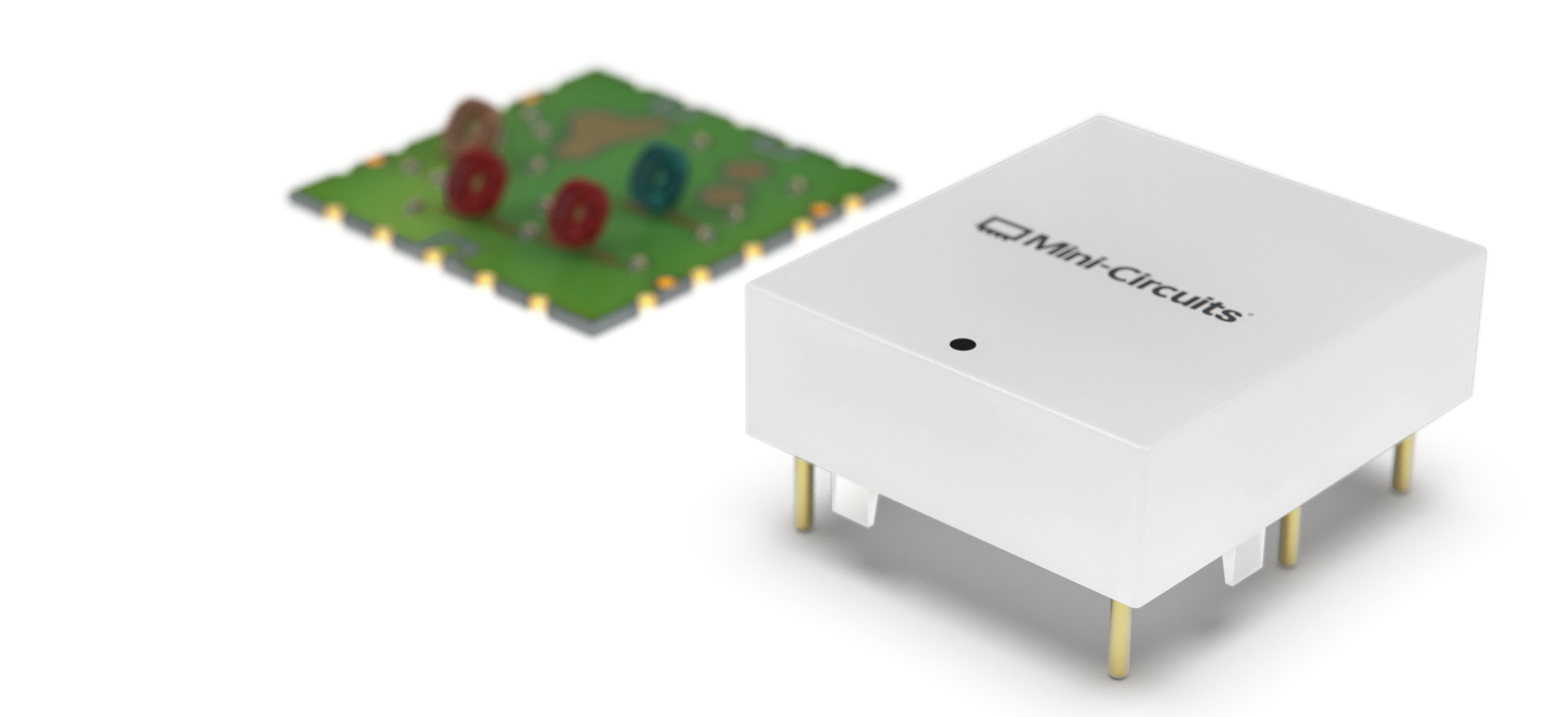
Image 2

Passives

Our 75Ω transformers, diplexers, couplers and other passive components have been essential in a wide range of architectures for decades, with performance, quality and service that have made Mini-Circuits a trusted partner to CATV industry customers.
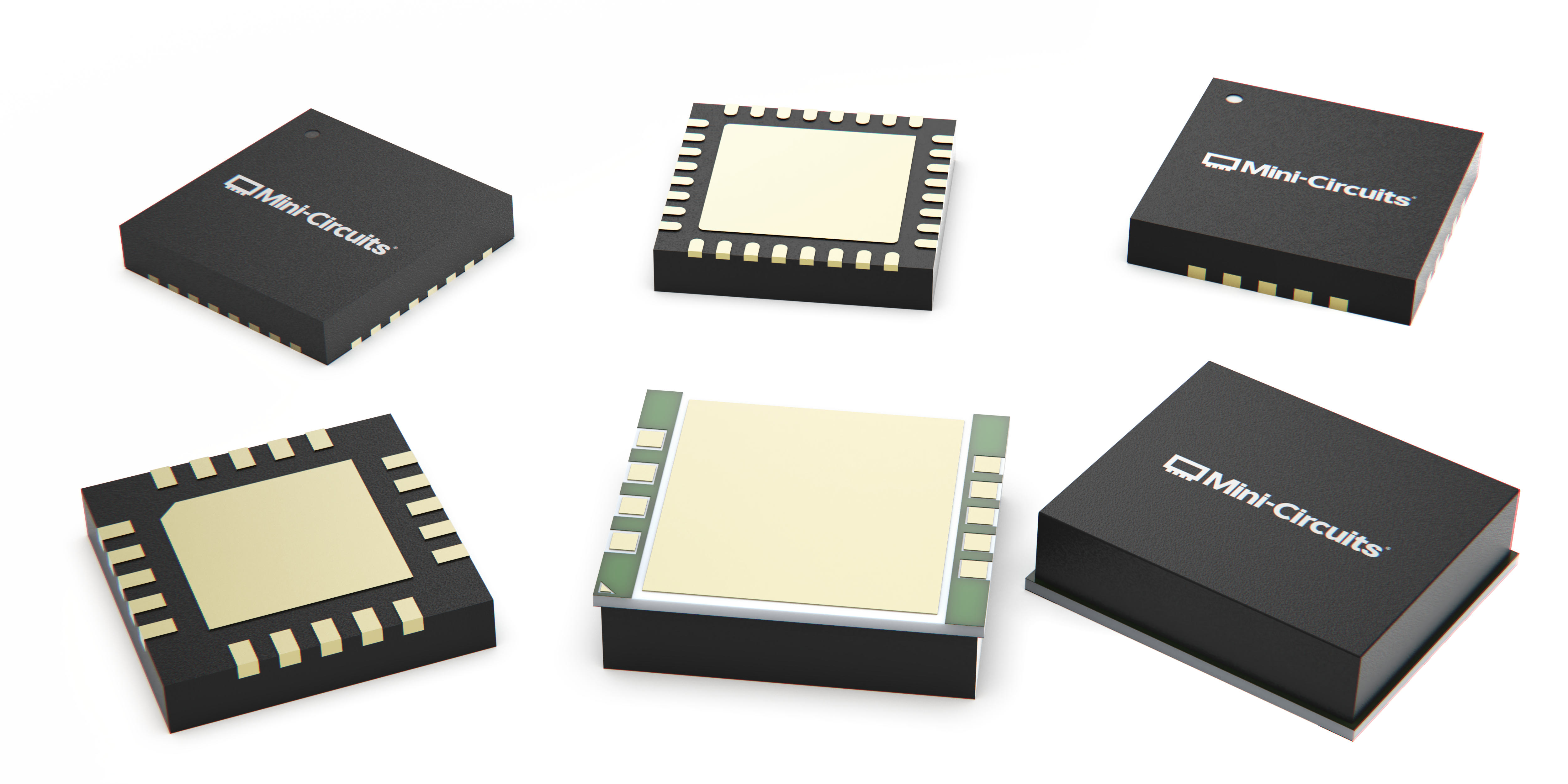
Image 2

Actives

Our new Santa Rosa MMIC Design Center builds on that foundation with industry-leading design capability for power amplifiers, multi-chip modules and hybrids for DOCSIS 3.1 and 4.0 systems utilizing ESD, FDX and other configurations.

Image 2

Peace of Mind

When you choose Mini-Circuits, you’re getting more than the right partner for your system. You’re getting a partner committed to your success.

· Accessible, engineering technical support
· Industry-leading supply-chain stability
· 55+ years in-house manufacturing and quality excellence

Product Line Synergy

Optimizing System Performance & Production Stability

Advanced in-house capability for 75Ω GaAs and GaN amplifier design and manufacturing together with an extensive portfolio of passive devices allows Mini-Circuits to optimize our designs for better overall system performance and production stability.

Typical Line Extender Amplifier Block Diagram

#1 TACH-182-75-xx+ (high power choke) #2 TDC-xx-182-xxx+ (test point couplers) #3 D4PLXEH1/EV1-x+ (DOCSIS 4.0 diplexers)
#4
TRS1-182-75-3+ (1.8 GHz transformer) #5 TC1-33-75G2+ (1.8 GHz transformer)

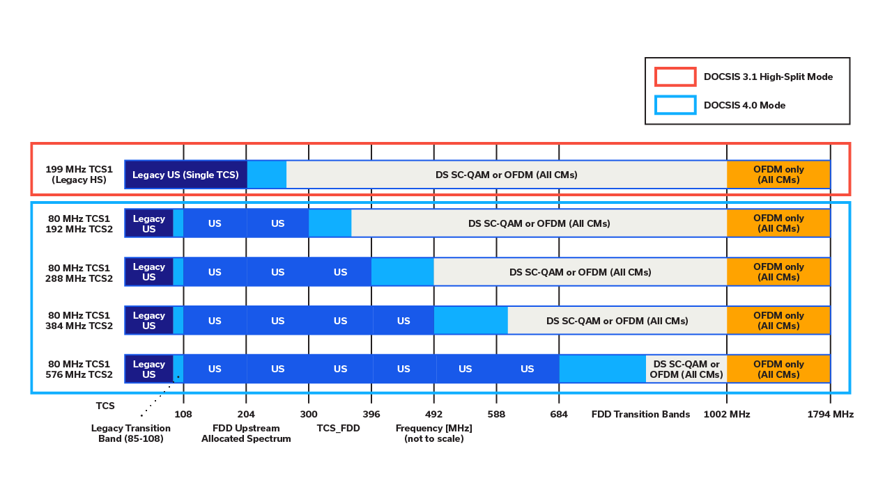
DOCSIS 4.0 Channel Split Options

Mini-Circuits offers solutions for virtually any system configuration including FDX (full-duplex) and ESD (extended-spectrum) DOCSIS 4.0 architectures. Our diplexers support any channel split for 1.2 GHz and 1.8 GHz systems.
Background Image

Product Portfolio

Actives

Broadband Amplifiers Actives
Model Name
Case Style
Freq Range (MHz)
Gain (dB)
NF (dB)
TCP (dBmV)
NPR MER (dB)
Voltage (V)
DC Current (mA)
32-Lead 5x5mm LFCSP
5-1794
19.1
3.0
67
48
5/8
250/375
32-Lead 5x5mm LFCSP
5-1794
25.8
3.8
67
51
5/8
300/470
20-Lead 4x4mm LFCSP
5-1794
17
2.1
58
53
5
250
Power Doubler Amplifiers
Model Name
Case Style
NF (dB)
Freq Range (MHz)
Gain (dB)
TCP (dBmV)
NPR (MER) (dB)
Voltage (V)
DC Current (mA)
9-Terminal 9x8mm LGA_CAV
3.3
45-1794
22.7
74
48
18/24
540
9-Terminal 9x8mm LGA_CAV
3
45-1218
25
74
50
24
480
Power Doubler Hybrid Modules
Model Name
Case Style
Freq Range (MHz)
Gain (dB)
NF (dB)
TCP (dBmV)
CSO (dBc)
Voltage (V)
DC Current (mA)
CTB (dBc)
SOT-115J
45-1218
25
3
74
-78
24
470/490
-80
SOT-115J
45-1218
25
3
74
-78
24
250/490
-80
SOT-115J
45-1218
24.5
3
76.8
-87
24/34
400/550
-82
SOT-115J
45-1218
26.7
3
76.8
-80
24/34
300/550
-80
Dual Matched Amplifiers
Model Name
Case Style
Freq Range (MHz)
Gain (dB)
NF (dB)
P1db (dBm)
OIP3 (dBm)
Voltage (V)
DC Current (mA)
4x4mm QFN-Style
40-1250
15.3
3.2
30.6
48.8
9
391
Linear Amplifiers
Model Name
Case Style
Freq Range (MHz)
Gain (dB)
NF (dB)
P1db (dBm)
OIP3 (dBm)
Voltage (V)
DC Current (mA)
SOT-89
50-1500
16.9
3.3
20.1
36.2
5
116
SOT-89
5-250
17.9
3.3
19.5
34.4
5
116
SOT-89
5-1500
15.5
2.8
23.8
41.4
9
115
Low Noise Amplifiers
Model Name
Case Style
Freq Range (MHz)
Gain (dB)
NF (dB)
P1db (dBm)
OIP3 (dBm)
Voltage (V)
DC Current (mA)
SOT-89
5-300
15.6
2.9
23.7/18.7
43.3/39.1
9.0/5.0
110/55
Bare Die
5-300
15.6
2.9
23.7/18.0
43.3/31.6
9.0/5.0
110/50.7

Passives

Voltage Variable Attenuators
Model Name
Case Style
Freq Range (MHz)
Attenuation Range (dB)
IP3 (dBm)
Return Loss (dB)
Max Control Voltage (V)
Max Control Current (mA)
HE1135
50-2000
0-30
49
25
8
40
Directional Couplers - Surface Mount
Model Name
Case Style
Freq Range (MHz)
Coupling (dB) Nom
Mainline Loss (dB)
Directivity (dB)
VSWR (:1)
Power Input Max (W)
TT2315
5-2350
20
0.65
20
1.2
1
DB714
5-2000
8.9
1.8
15
1.5
1
DB1627
5-2000
8.9
1.8
15
1.5
1
DB1627
5-2000
16.5
1.3
22
1.2
1
TT2315
5-1800
7.5
2.7
12
1.29
1
TT2315
5-1800
10
1.3
20
1.2
1
TT2315-3
5-1800
16.3
1.1
12
1.22
2
AT790-1
5-1500
13.2
0.7
19
1.3
1
AT1030
5-1500
13.2
1.4
19
1.3
1
AT1642
5-1500
13.2
1.4
19
1.3
1
AT1667-1
5-1500
13.2
0.7
19
1.3
1
AT790-1
5-1500
16.3
1.3
21
1.3
1
AT1030
5-1500
16.3
1.3
21
1.3
1
AT1642
5-1500
16.3
1.3
21
1.3
1
AT1667-1
5-1500
16.3
1.3
21
1.3
1
CD542
5-1250
7.9
1.6
17
1.2
1
CD542
5-1250
17
0.8
12
1.15
1
CD542
5-1250
19.7
0.5
23
1.15
1
CD636
5-1250
25
0.1
25
1.2
1
AT790-1
5-1250
6.8
2.2
17
1.4
1
AT1030
5-1250
6.8
2.2
17
1.4
1
AT1642
5-1250
6.8
2.2
17
1.4
1
AT1667-1
5-1250
6.8
2.2
17
1.4
1
AT790-1
5-1250
20.5
0.8
19
1.4
1
AT1667-1
5-1250
20.5
0.8
19
1.4
1
TT2315
5-1250
10
1.2
20
1.22
1
DB1627
5-1250
6.7
2.3
12
1.43
0.5
AT1521
5-1250
10
1.5
15
1.17
1
DB1627
5-1250
12.7
1
15
1.17
1
DB1627
5-1250
16.5
1.5
22
1.33
1
DB1627
5-1250
17.5
1
22
1.17
1
DB1627
5-1218
16
0.9
16
1.3
1
AT790-1
5-1200
9.3
1.3
20
1.3
0.7
AT1030
5-1200
9.3
1.3
20
1.3
0.7
AT1642
5-1200
9.3
1.3
20
1.3
0.7
AT1667-1
5-1200
9.3
1.3
20
1.3
0.7
AT790-1
5-1200
12
1.1
19
1.3
0.5
AT1030
5-1200
12
1.1
19
1.3
0.5
AT1642
5-1200
12
1.1
19
1.3
0.5
AT1667-1
5-1200
12
1.1
19
1.3
0.5
DB714
40-1200
20
0.6
23
1.15
1
DB1627
40-1200
20
0.6
23
1.15
1
CD542
20-1000
6.6
2.1
15
1.3
0.5
CD636
40-1000
20.5
0.6
20
1.1
1
AT790-1
5-1000
10.5
0.7
20
1.3
1
AT1030
5-1000
10.5
0.7
20
1.3
1
AT1642
5-1000
10.5
0.7
20
1.3
1
AT1667-1
5-1000
10.5
0.7
20
1.3
1
AT790-1
5-1000
18.2
0.8
21
1.3
1
AT1030
5-1000
18.2
0.8
21
1.3
1
AT1642
5-1000
18.2
0.8
21
1.3
1
AT1667-1
5-1000
18.2
0.8
21
1.3
1
AT224-1
5-1000
9.9
1.1
20
1.25
1
AT1521
5-1000
9.9
1.1
20
1.25
1
DB714
5-1000
13
0.8
15
1.2
1
DB1627
5-1000
13
0.8
15
1.2
1
DB714
10-1000
18
0.7
22
1.2
1
DB1627
10-1000
18
0.7
22
1.2
1
DB714
10-750
10.5
1.4
18
1.3
1
DB1627
10-750
10.5
1.4
18
1.3
1
BH292
2-250
19.2
0.4
30
1.1
1
Directional Couplers - Connectorized
Model Name
Case Style
Freq Range (MHz)
Coupling (dB) Nom
Mainline Loss (dB)
Directivity (dB)
VSWR (:1)
Power Input Max (W)
F14
800-1750
19.8
0.4
22
1.2
1
K18
5-1500
16.5
1.1
24
1.3
1
K18
5-1000
18.5
0.85
23
1.3
1
M22
1-250
10.5
1.1
30
2
4
K18
10-250
19.3
0.3
29
1.2
2
M22
1-150
19.5
0.35
25
2
4
M22
50-100
10.5
1.1
35
1.3
4
M22
55-90
18.6
0.4
35
1.2
4
Splitter / Combiners - Surface Mount
Model Name
Case Style
No. of Ways
Freq Range (MHz)
Isolation (dB)
Insertion Loss (dB)
Phase Unbalance Deg
Amplitude Unbalance (dB)
Power Input (W) As Splitter Max
AH202-2
2
2-2750
20
0.5
2
0.2
0.5
AT3081
2
5-2300
22
0.8
2
0.1
0.5
CD542
2
5-2000
16
0.5
4
0.3
0.5
DB1627
2
10-1800
26
0.8
2
0.15
0.5
DZ943
4
10-1500
19
1.2
9
0.9
0.5
AH202
3
5-1500
24
1
2
0.4
1
DB1627
2
5-1500
28
0.8
1.5
0.25
0.5
TT1491-1
2
1-1250
21
0.8
1.5
0.25
1
DB1627
2
5-1250
24
0.9
1.5
0.4
0.5
CD636
2
5-1200
28
0.7
4
0.3
1
TT1491-2
2
5-1200
25
0.6
2
0.2
1
AH202
3
20-1200
22
1.2
2
0.7
1
CD542
2
50-1000
24
0.7
2
0.2
0.5
TT1491-1
2
5-1000
25
0.6
3
0.3
1
BH292
2
20-1000
29
0.4
2
0.2
1
AT790
2
10-1000
28
0.6
3
0.6
0.5
AT1029
2
10-1000
28
0.6
3
0.6
0.5
AT1739
2
10-1000
28
0.6
3
0.6
0.5
AT790
2
5-1000
24
0.6
3
0.5
0.5
AT1667
2
5-1000
24
0.6
3
0.5
0.5
DZ943
4
10-1000
30
1.5
9
0.9
0.5
YY161
4
10-1000
32
0.65
6
0.4
1
DB714
2
5-1000
29
0.3
4
0.6
0.5
DB1627
2
5-1000
29
0.3
4
0.6
0.5
BH292
2
5-500
35
0.15
2
0.2
1
QQQ130
2
2-500
35
0.35
2
0.2
1
QQQ569
2
2-500
35
0.35
2
0.2
1
Splitter / Combiners - Connectorized
Model Name
Case Style
No. of Ways
Freq Range (MHz)
Isolation (dB)
Insertion Loss (dB)
Phase Unbalance Deg
Amplitude Unbalance (dB)
Power Input (W) As Splitter Max
F14
2
5-2500
26
0.6
3
0.4
0.5
F53
2
700-2450
25
0.5
1
0.1
10
Z41
8
600-2400
27
0.7
3
0.3
10
UU188
4
950-2200
23
0.9
2.7
0.3
10
Z41
8
950-2200
24
0.7
-
0.3
10
F14
2
910-2150
30
0.2
2
0.4
5
K18
2
DC-2000
6.6
0.3
2
0.2
0.75
J17
3
1-1000
27
0.4
6
0.7
1
G15
4
10-1000
38
0.6
-
0.3
1
G15
4
5-1000
36
0.5
3
0.2
1
K18
2
5-600
45
0.27
2
0.3
1
R67
12
10-500
24
1
-
0.5
1
UU188
4
0.25-300
36
0.3
2
0.2
1
K18
2
0.25-300
30
0.4
3
0.2
1
M22
2
0.25-300
30
0.4
3
0.2
1
Q28
6
1-200
30
0.75
6
0.4
1
R31
24
1-200
33
0.8
-
0.4
1
P25
3
1-200
35
0.4
3
0.2
1
G15
4
50-90
34
0.3
6
0.15
1
R29
8
50-90
30
1
2
0.2
1
M22
2
55-85
35
0.3
1
0.1
1
M22
2
0.002-60
30
0.3
3
0.25
1
Diplexers - Surface Mount
Model Name
Channel
Rejection (dB)
Case Style
Passband (MHz)
Cross Over Isolation (dB)
Interface
Passband IL (dB)
Low Pass
50 @ 258-1220
NU1620
DC-204
40
SMT
1
High Pass
50 @ DC-204
NU1620
258-1220
40
SMT
1
Low Pass
50 @ 54-1220
NU1620
DC-42
-
SMT
0.8
High Pass
50 @ DC-42
NU1620
54-1220
-
SMT
0.8
LOW PASS
50 @ 85-1220
NU1620
5-65
40
SMT
1.0
HIGH PASS
55 @ 5-65
NU1620
85-1220
40
SMT
1.0
LOW PASS
48 @ 102-1220
NU1620
5-85
9
SMT
0.7
HIGH PASS
48 @ 5-85
NU1620
102-1220
9
SMT
1
LOW PASS
55 @ 5-85
NU1620
5-85
41
SMT
1.2
HIGH PASS
45 @ 102-1220
NU1620
102-1220
41
SMT
1.3
Switches
Model Name
Case Style
Type
Freq Low (GHz)
Freq Hi (GHz)
Driver
Insertion Loss (dB)
Insertion Loss (dB) Max
One Compression (dBm)
In Out Isolation (dB)
In Out Isolation (dB) Min
MT1818
SPDT
3000
3000
CMOS
0.4
0.64
35
35
28
MT1818
SPDT
3000
3000
CMOS
0.3
0.64
35
35
28
MT1817
SP4T
2000
2000
CMOS
0.8
1.3
35
32
22
MT1817
SP5T
2000
2000
CMOS
0.8
1.3
35
32
22
MT1817
SP6T
2000
2000
CMOS
0.8
1.3
35
32
22
Transformers
Model Name
Case Style
Single Ended To Single Ended
Single Ended To Balanced
Balanced To Balanced
Center Tap
DC Isolation
Freq Rang (MHz)
Impedance Ratio Sec Pri
Technology
SN2595
N
N
N
N
N
10-3000
1.33
Core & Wire
AT224-1
N
Y
Y
N
N
4.5-3000
1
Core & Wire
AT1521
N
Y
Y
N
N
4.5-3000
1
Core & Wire
AT224-3
N
Y
Y
N
N
5-3000
1
Core & Wire
GU2939
N
N
N
N
N
30-3000
1
Core & Wire
AT224-1A
N
Y
Y
N
N
5 - 2800
1.33
Core & Wire
AT1521
N
Y
Y
N
N
5 - 2800
1.33
Core & Wire
AT577-1
N
Y
Y
N
N
10 - 2200
1
Core & Wire
CD542
N
Y
Y
N
N
5-1800
1
Core & Wire
AT1521
N
N
N
Y
N
5-1800
1
Core & Wire
AT1521
N
N
N
Y
N
5-1800
1.33
Core & Wire
DB1627
N
Y
Y
N
N
50-1800
2
Core & Wire
TT1618-1
N
Y
Y
N
N
10-1800
1
Core & Wire
CD542
N
Y
Y
N
N
10-1500
1
Core & Wire
FV1206-1
N
N
N
N
Y
950-1450
1
LTCC
AT1521
N
Y
Y
Y
N
40-1250
4
Core & Wire
GU2644
N
N
N
N
N
5-1250
1
Core & Wire
GU2644
N
Y
Y
N
N
20-1250
1
Core & Wire
TT2315-3
N
Y
Y
Y
N
40-1250
2.78
Core & Wire
TT240
N
Y
Y
Y
Y
20-1250
2
Core & Wire
TT1618
N
N
N
N
N
5-1200
2
Core & Wire
CD542
N
Y
Y
N
N
0.5-1000
1
Core & Wire
BH292
N
Y
Y
Y
Y
50-1000
2
Core & Wire
BH292
N
Y
Y
Y
Y
50-1000
2
Core & Wire
CD542
N
Y
Y
Y
Y
0.4-800
1
Core & Wire
AT1521
N
Y
Y
Y
Y
0.6-600
4
Core & Wire
AT224-1A
N
Y
Y
Y
Y
3-500
1.33
Core & Wire
AT1521
N
Y
Y
Y
Y
3-500
1.33
Core & Wire
AT224-1
Y
N
N
N
N
0.3-475
0.11
Core & Wire
AT1521
Y
N
N
N
N
0.3-475
0.11
Core & Wire
CD542
N
Y
Y
Y
Y
1-400
1
Core & Wire
AT577
N
Y
Y
Y
Y
1-400
1.33
Core & Wire
AT1521
N
Y
Y
Y
Y
5-120
1
Core & Wire

Test Tools & Accessories

75Ω Power Sensor
Model Name
Case Style
Control Interface
Measurement Type
Frequency Range (MHz)
Input Power Min (dBm)
Input Power Max (dBm)
Dynamic Range (dB)
Measurement Speed Ms
JL1337
USB
CW 75
0.1 - 2500
-30
20
50
30
75Ω Test Cables
Model Name
Connector 1 Type
Connector 1 Gender
Connector 2 Type
Connector 2 Gender
Length (ft)
Frequency Range (MHz)
Insertion Loss (dB)
F-Type
Male
F-Type
Male
6.0
DC - 3000
1.43
N-Type
Male
N-Type
Male
6.0
DC - 3000
1.43
N-Type
Male
N-Type
Male
4.0
DC - 3000
0.8
F-Type
Male
F-Type
Male
3.28
DC - 3000
0.89
F-Type
Male
F-Type
Male
3.0
DC - 3000
0.77
N-Type
Male
N-Type
Male
3.0
DC - 3000
0.7
F-Type
Male
F-Type
Male
2.0
DC - 3000
0.61
Matching Pads
Model Name
Case Style
Freq Range Low (MHz)
Freq Range High (MHz)
Nom Attenuation (dB)
Attenuation Flatness (dB) Typ.
VSWR (:1) Typ.
Connector Typ.
Connector 50 Ohm
Connector 75 Ohm
FF747
DC
2000
5.7±0.10
0.3
1.22
BNC
Female
Male
FF747
DC
2000
5.7±0.10
0.3
1.22
BNC
Male
Female
FF1833
DC
3000
5.9
0.2
1.17
F-SMA
SMA-Female
F-Female
FF2586
DC
3000
5.7
0.2
1.2
SMA-F
SMA-Female
F-Male
FF779
DC
3000
5.7±0.15
0.3
1.3
TYPE N
Female
Male
FF779
DC
3000
5.7±0.15
0.3
1.05
TYPE N
Female
Male
FF779
DC
3000
1.7
0.2
1.15
TYPE N
Male
Female
FF779
DC
3000
5.7±0.15
0.3
1.05
TYPE N
Male
Female
H16
DC
2500
5.9
-
1.2
SMA-F
SMA-Female
F-Male

Contact Us