
Semiconductor Quality Overview
Introduction
Mini-Circuits, Inc.is committed to building products which meet or exceed customers' expectations. As we are ISO 9001:2000 and ISO 14001:2004 certified, we produce products using the highest quality and reliability standards.
This section will highlight key differences in the approach between Mini-Circuits' and typical market products. To be the world leader in RF and microwave products, we always insist on consistent performance, world-class quality and outstanding reliability in our products. As one of the few suppliers who own and manage their design and manufacturing facilities, Mini-Circuits is able to provide the most consistent, highest quality products to our customers.
Quality Designed In
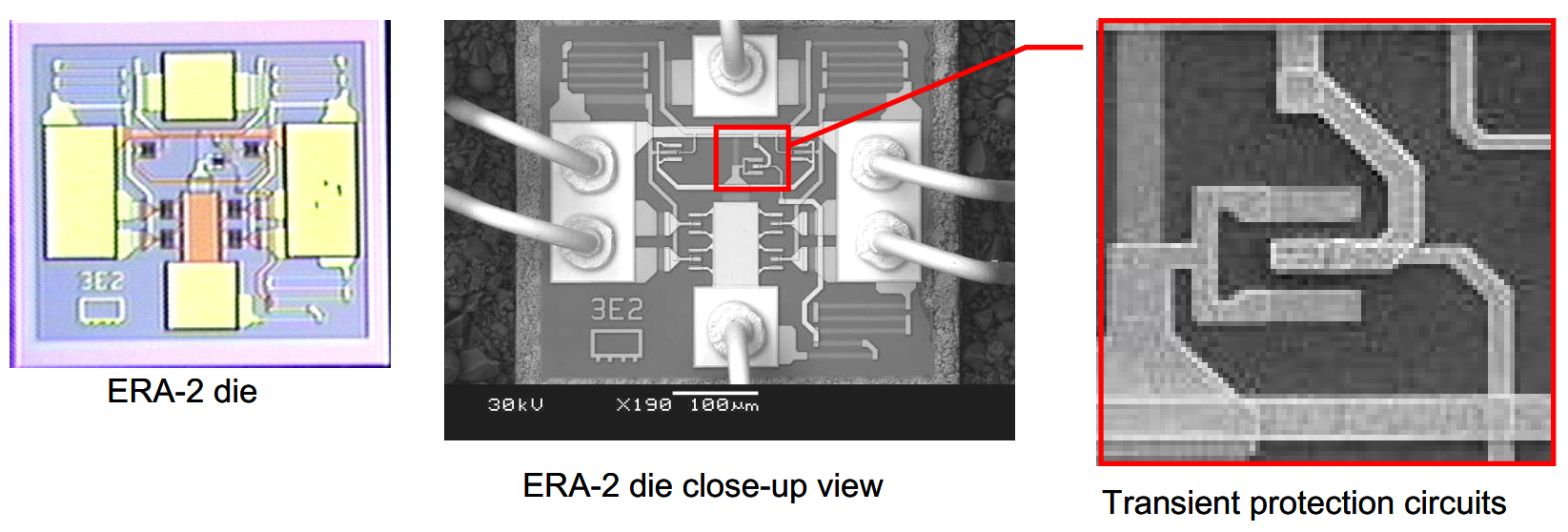
Transient Current Protection Circuit
The EXTRA-RELIABLE Amplifiers (ERA) Series amplifiers are based on InGaP HBT (Heterojunction-bipolar-transistor) technology and achieve wideband high gain performance via a Darlington configuration. HBT technology provides many benefits that are not available in commonly used MESFET devices, namely single supply voltage operation and unconditional stability through the entire amplifier frequency range.
However, current transients that occur during power-up can cause damage in any high gain amplifier that uses a Darlington configuration. To address this issue, we design amplifiers with transient current protection circuits, which prevent damaging of the circuits by unforeseen electrical spikes, while still providing state-of-the-art performance.
Die Layout Features
- Heat sources are separated to minimize heat coupling.
- Metal structures provide better heat sinks
- Double bonds on ground provides better grounding and heat dissipation.
Material Selection
Materials used for assembly have been carefully chosen to meet moisture sensitivity standards and improve thermal conductivity performance. Mini-Circuits' stringent material selection improves GaAs thermal conductivity to prevent performance degradation and catastrophic failures.
| Material | Mini-circuits | Typical Market Products | Benefits Compared to Typical Market Products |
|---|---|---|---|
|
Mold Compound |
150 X 10-2 W/m° K |
88 X 10-2 W/m° K |
2X more thermal conductivty |
|
|
45 W/m° K |
2.5 W/m° K |
18X more thermal conductivty |
|
Leadframe |
(Copper Alloy) 259.0 W/m° K |
(Alloy42) 14.7 W/m° K |
18X more thermal conductivty |
Quality Manufacturing

Electronic Wafer Mapping
Every die on our wafers is individually tested and electronically mapped according to key performance parameters, enabling us to select specific die for specific production requirements. This results in products with very consistent and tightly distributed performance.

In-Process Controls
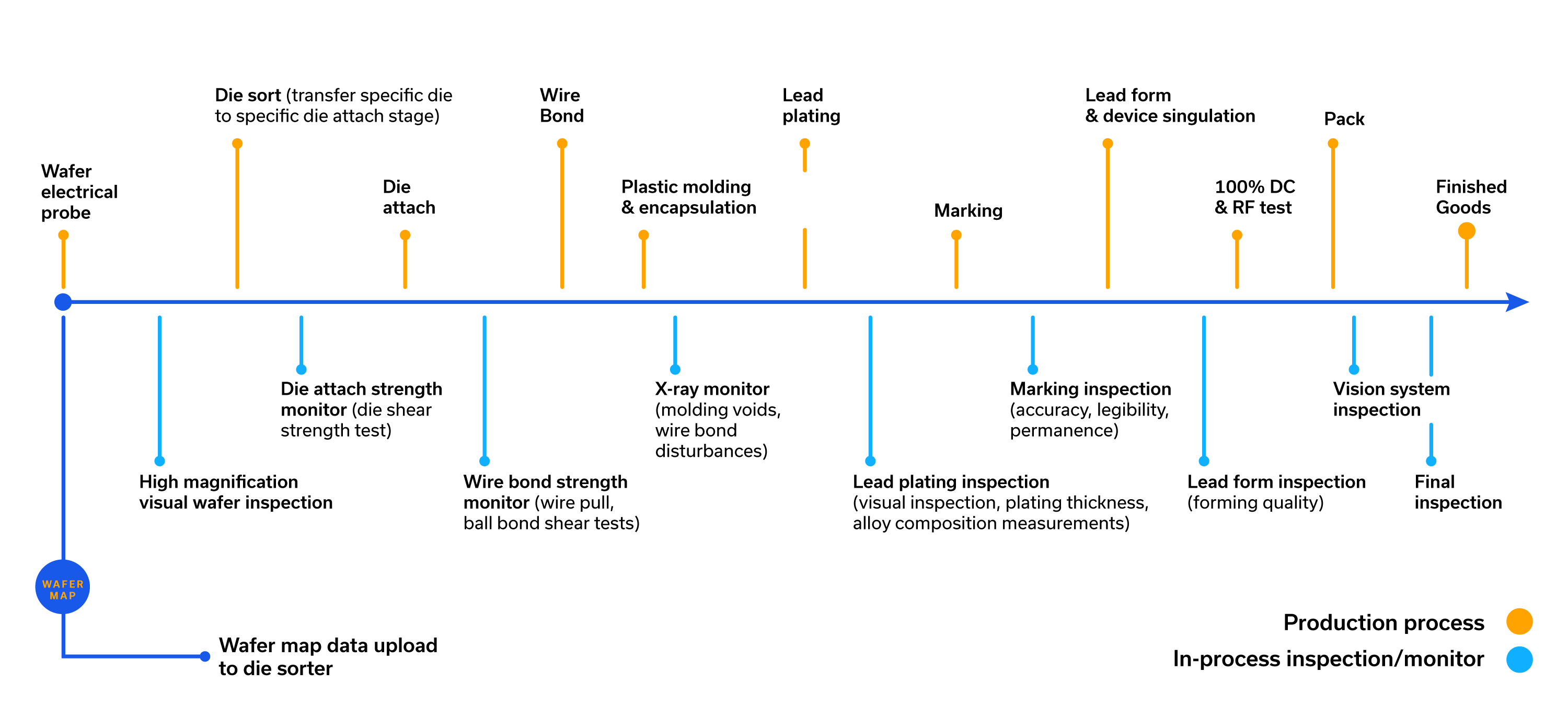
Wafer Mapping
Process Monitors
In-Process Inspections
Material Selection
All Mini-Circuits semiconductor products are offered in RoHS compliant models.
Performance Monitors
Benefits
Our extensive in-process controls provide early detection of process variation and potential quality issues, providing crucial information for real-time process corrections.
|
NO. |
Process |
Characteristics |
Sample Size |
Frequency |
Acceptance Criteria |
|---|---|---|---|---|---|
|
1 |
Die Attach |
Die Tilt |
1 unit/machine |
1x/Day/Machine Set up |
5 mils |
|
Die Bond Line Thickness |
1 unit/machine |
Min 0.3 mils |
|||
|
Die Shear Strength |
4 units/machine |
0.25 kgF |
|||
|
2 |
Wire Bond |
Ball Size |
2 Units; 2 balls/unit/machine |
1x/Day/Machine Set up |
2.50 to 3.50 mils |
|
Wire Loop Height |
5 Units; 1 wire/unit for each Ground & lead bond |
5.0 +/- 1.0 mils (lower loop) 6.0 +/- 1.0 mils (higher loop) |
|||
|
Wire Pull Strength |
2 wires/unit; 4 units/machine |
4 gF |
|||
|
Ball Shear Strength |
2 balls/unit; 4 units/machine |
25 gF |
|||
|
3 |
Molding |
Wire Sweep |
1 wire/unit; 5 units/machine |
1x/day/machine set up |
< 12%> |
|
4 |
Plating |
Plating Thickness |
2 strips; 5 readings/strip |
Every Lot |
300 micro inch |
|
Scratch Test |
8 leads |
No Peeling Plating |
|||
|
Adhesion Test |
8 Leads |
No Peeling Plating |
|||
|
Bend Test |
5 Leads |
No Peeling Plating |
|||
|
Solderability Test |
8 Leads |
< 95% Solder Coverage |
|||
|
5 |
Ink Marking |
Resistance to Solvent |
20 units/solvent |
Every Shift |
No Smearing or Marking |
|
6 |
Trim/Form/Singulate |
Package Outline |
5 Units |
Every Lot |
Per Package Outline Specification |
|
Lead Coplanarity |
5 Units |
0.1 mm |
|||
|
7 |
Test |
At Mini-Circuits, we do not consider it good enough to ship products that just meet specifications. To pursue our goal of exceeding out customers expectations, we test our products to 4.5 sigma limits instead of the specification limits. |
|||
Dynamic Test Specifications
In pursuit of our goal to exceed our customers' expectations, we test our products to statistically generated 4.5 sigma limits instead of the specification limits. As a result, the products that are shipped to our customers are very consistent in performance with tight distributions.
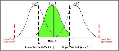
Diagram illustrates 4.5 sigma limits used instead of specification limits.
Only products from the shaded area for lot 1 will be tested good and shipped to customers.
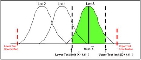
Diagram illustrates 4.5 sigma limits used instead of specification limits.
Only products from the shaded area for lot 3 will be tested good and shipped to customers.
Reliability Testing
New Product Introduction / Qualification
Extensive qualification processes for new products. Every new product goes through stringent JEDEC and MIL-STD stress and accelerated-life tests. Every product is subjected to destructive stress tests to add to our understanding of each product's capabilities and operating limitations.
Ongoing Monitoring
In addition to product qualifications, Mini-Circuits commits to regular monitors of our products to ensure that our high standards in quality and reliability are maintained and achieved over the product lifetime.
Our Reliability Database captures and tracks the reliability performance of our manufacturing lots over time.
This database provides a complete record of each product's reliability history.
Example: Moisture Sensitivity Level 1 (MSL 1) rating in accordance with IPC/JEDEC STD-020C
In addition to product qualifications, Mini-Circuits commits to regular monitors of our products to ensure that our high standards in quality and reliability are maintained and achieved over the product lifetime.
Our Reliability Database captures and tracks the reliability performance of our manufacturing lots over time.
This database provides a complete record of each product's reliability history.
Example:
Moisture Sensitivity Level 1 (MSL 1) rating in accordance with IPC/JEDECSTD-020C.
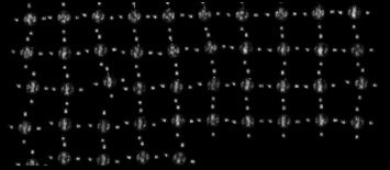
The following shows C-Mode Scanning Acoustic Microscope (C-SAM) photos of a device before and after moisture sensitivity level 1 (MSL 1) tests
Before MSL-1 Level Testing : Top View
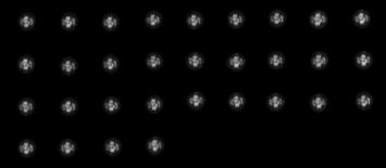
After MSL-1 Level Testing : Top View
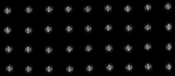
Before MSL-1 Level Testing : Bottom View
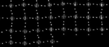
After MSL-1 Level Testing : Bottom View
The table below shows delamination determination after MSL 1 pre-conditioning tests. Monitoring results have shown no delamination detected over the past 5 years.
|
Quarter / Year |
Delamination Study |
|
|
Quantity Tested |
Quantity Failed |
|
|
2005 |
6408 |
0 |
|
2006 |
5460 |
0 |
|
2007 |
7516 |
0 |
|
Q1 / 2008 |
1560 |
0 |
|
Q2 / 2008 |
1799 |
0 |
|
Q3 / 2008 |
1821 |
0 |
|
Q4 / 2008 |
2342 |
0 |
|
Q1 / 2009 |
2314 |
0 |
|
Q2 / 2009 |
2288 |
0 |
|
Q3 / 2009 |
2374 |
0 |
|
Q4 / 2009 |
2096 |
0 |
Additional Tests and Evaluations Conducted by Mini-Circuits
| No | Test Type | Reference Document | Application |
| 1 | Visual Inspection | Mini-Circuits Specification | External package inspection |
| 2 | Room temperature Electrical test | Mini-Circuits Specification | Electrical test to data sheet specifications |
| 3 | Scanning Acoustic Microscope (SAM) Analysis | Jedec Standard, J-Std-020C | To detect delamination or gap between materials |
| 4 | Resisitance to Soldering Heat | Jedec Standard, J-Std-020C | To simulate surface mount assembly processes |
| 5 | Moisture Sensitivity Level | Jedec Standard, J-Std-020C | To determine the moisture sensitivity level of a package |
| 6 | Temperature Cycle | Military Standard, Mil-Std-883E, Method 1010.7 | Test the ability to withstand altering temperatures |
| 7 | Autoclave | Jedec Standard, JESD22-A102-C | To evaluate the ability to withstand moisture resistance |
| 8 | High Temperature Storage | Jedec Standard, JESD22-A102-C (Extended to 5000 hours) | To evaluate the effect of device storage at elevated temperatures |
| 9 | Humidity Steady state | Military Standard, Mil-Std-202F, method 103B condition C | To evaluate at high humidity and at an elevated temperature |
| 10 | Temperature and Humidity test without Bias | Jedec Standard, JESD22-A101-B | To evaluate storage in a humid environment |
| 11 | Whisker Growth Test | Jedec Standard, JESD22-A121 | To study the whisker growth on finishes containing tin |
| 12 | Thermal Diode | Mini-Circuits Specification | MMIC junction temperature measurement |
| 13 | Solderability Test, Solder Dip Method | Military Standard, Mil-Std-202F, Method 103B condition C | To determine the solderability of a device |
| 14 | Solderability Test, Surface Mount Method | Jedec Standard, JESD22-B102-D | To determine the solderability of a device |
| 15 | Lead Integrity Test | Military Standard, Mil-Std-883E, Method 2004.5 | to evaluate the integrity of device leads |
| 16 | Tape Peel test | Mini-Circuits Specification | To evaluate plating adhesion |
| 17 | Scratch Test | Mini-Circuits Specification | To evaluate plating adhesion |
| 18 | Resistance to Solvents | Military Standard, Mil-Std-202F, Method 103B condition C | To evaluate the link marking the encapsulant materials |
| 19 | Welding Test | Mini-Circuits Specification | To determine weldability and weld peel strength |
| 20 | Plating Thickness | Mini-Circuits Specification | Thickness Measurement |
| 21 | Plating Composition | Mini-Circuits Specification | Composition Measurement |
| 22 | X-Ray Analysis | Mini-Circuits Specification | Internal Package Inspection |
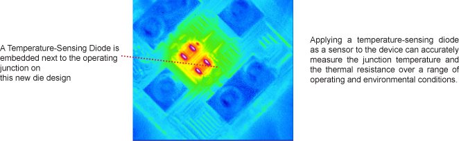
MMIC Amplifier Junction Temperature Measurement and Monitoring Program
Temperature has a direct impact on the operating performance and reliability of semiconductor devices. Devices that operate at high junction temperatures for a long period of time can sustain permanent damage and shorten lifetimes.
At Mini-Circuits, MMIC amplifier junction temperature measurement and monitoring is performed on every production wafer lot to ensure our customers receive products with the highest quality, reliability and performance.
YEAR |
Junction Temperature Measurement Study |
|
|---|---|---|
Measured Wafer Lots |
Quantity Failed |
|
|
2005 |
52 |
0 |
|
2006 |
154 |
0 |
|
2007 |
132 |
0 |
|
2008 |
196 |
0 |
|
2009 |
124 |
0 |
Reliability Monitoring is used to evaluate product reliability performance throughout a product's lifetime. Comprehensive qualifications are performed for process and materials changes during the product's lifetime. A Reliability Database tracks the reliability performance over time and archives all qualification data. This database provides a complete record of each product's reliability history.
Physical Analysis
Non-Destructive Analysis Techniques
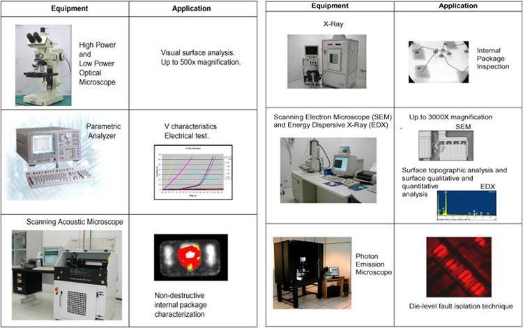
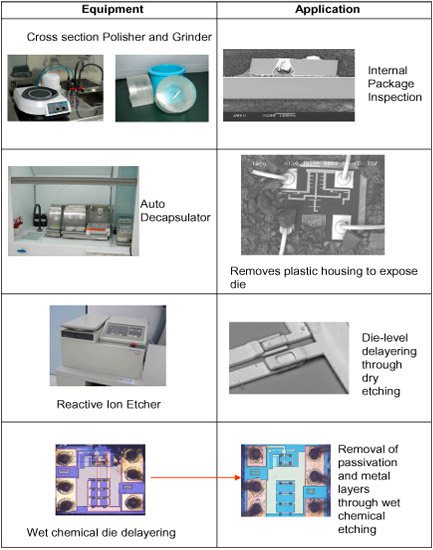
Destructive Analysis Techniques
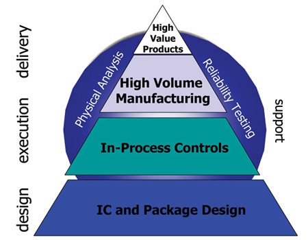
High Volume Delivery of High Valued Products Model

Subscribe to receive Mini-Circuits News